


 It’s Only Common Sense: OCCAM—the Time Is Now
 Marcy's Musings: The Growing Industry
 Dan’s Biz Bookshelf: Seeing the How
Selecting Flex Materials: Do Your Homework
May 25, 2023 | Mike Morando, PFCEstimated reading time: 3 minutes

Flex circuits have become more complex in the last decade, driven in part by shrinking designs and components’ higher speeds and signal integrity requirements. Choosing the correct materials for your flex and rigid-flex circuits is a critical part of the design process.
While the layout of the circuit gives us much of the electrical characteristics of the design, your choice of materials can affect the mechanical and electrical characteristics of the circuit. Material choices affect not only the design of the circuit for its environment, but also the manufacturing and assembly processes.
Flex Material Choices: Comprehensive
Your manufacturer’s expertise in flex materials is a true asset, especially with today’s complex multilayer flex and rigid-flex circuits, as well as high speed and signal integrity requirements. In my opinion, it is a requirement to work with your flex manufacturer to communicate all aspects of the circuit, as well as the environment the circuit may encounter.
Here is a list of flex material criteria that you should discuss with your manufacturer.
- Approved process: What materials has your vendor run through their process and approved? All flex vendors etch copper on polyimide, but material availability, equipment, processes, and even humidity can affect processing flex and rigid-flex. Make sure your vendor is familiar with the materials they are proposing and have approved their process. You don’t want your project to become a science experiment.
- UL requirements: Does the flex need to be UL-approved? What material stacks does your vendor have in their UL library? UL approval is affected by the flammability of the adhesives used in their proposed stack.
- Flex stack: Polyimide and copper adhesive-based or adhesive-less? Adhesive-based materials use acrylic adhesive to adhere the copper to the polyimide material. The acrylic adhesive has disadvantages such as via cracking and squeeze-out, and it is more apt to absorb moisture.
- Electrical Characteristics:
- Power: Copper thickness, temperature, and adhesive requirements to meet your current requirements.
- Impedance/signal integrity: Your manufacturer should recommend trace, space, and polyimide thickness, as well as appropriate adhesive requirements.
- Signal speed/low loss: In most cases, standard flex materials can be used up to about 10 Gbps. For speeds above 10 Gbps, your manufacturer should recommend alternative materials. PTFE and LCP are the current popular choices. In addition to the base materials, different adhesives and epoxy films can be used in the lamination process that provide low Dk and thinner material stacks. In addition, there are high-speed coverlays to be considered and tested, depending on the Dk values required.
- Shielding: Material stacks may require shielding either for EMI or for support of high-speed low-loss solutions. You can also add more copper layers, cross hatching, metallized epoxies, and some of the new ferrous cover materials. Adding materials to the stack will always affect the bending of the circuit, so keep that in mind.
- Bend radius: IPC standards recommend the bend radius of a circuit to be 10X the thickness of the material. This likely affects material choices and design. The bend of the circuit may be in a particular section of the circuit only. Share the location of the bend and the number of times the circuit will bend. Your vendor should propose to reduce thicknesses in the required areas by adjusting the material thicknesses.
- Temperature: What temperature is the flex going to encounter? High temperatures affect the adhesives used. Make sure to discuss the environment with your vendor. We have used aluminum for heat dissipation.
- Stiffeners: FR-4 is the most popular stiffener material. It is used for stiffening SMT areas, through-hole connectors, and for ZIF connector interfaces, but we have used additional polyimide as a stiffener, and ceramic and stainless steel, depending on the requirements.
- Coverlay and solder mask: Coverlay (polyimide layer and adhesive over traces) is used in most flex areas, but now with the shrinking of components, the use of solder mask in dense areas has become more common. Remember: Solder mask can crack when bent.
- Plating: We are seeing more requirements for wire bonding on flex. Electroplated soft gold or ENEPIG are the best choices. ENIG is the most common for standard assembly.
Ultimately, after working with your manufacturer and going through this list, you should end up with a material stack that meets all your requirements.
This article originally appeared in the May 2023 issue of Design007 Magazine.
Share on:


Suggested Items
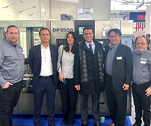
Taiyo Circuit Automation Installs New DP3500 into Fuba Printed Circuits, Tunisia
04/25/2024 | Taiyo Circuit AutomationTaiyo Circuit Automation is proud to be partnered with Fuba Printed Circuits, Tunisia part of the OneTech Group of companies, a leading printed circuit board manufacturer based out of Bizerte, Tunisia, on their first installation of Taiyo Circuit Automation DP3500 coater.
Vicor Power Orders Hentec Industries/RPS Automation Pulsar Solderability Testing System
04/24/2024 | Hentec Industries/RPS AutomationHentec Industries/RPS Automation, a leading manufacturer of selective soldering, lead tinning and solderability test equipment, is pleased to announce that Vicor Power has finalized the purchase of a Pulsar solderability testing system.
AIM Solder’s Dillon Zhu to Present on Ultraminiature Soldering at SMTA China East
04/22/2024 | AIMAIM Solder, a leading global manufacturer of solder assembly materials for the electronics industry, is pleased to announce that Dillon Zhu will present on the topic: Ultraminiature Soldering: Techniques, Technologies, and Standards at SMTA China East. This event is being held at the Shanghai World Expo Exhibition & Convention Center from April 24-25.
AIM to Highlight NC259FPA Ultrafine No Clean Solder Paste at SMTA Wisconsin Expo & Tech Forum
04/18/2024 | AIMAIM Solder, a leading global manufacturer of solder assembly materials for the electronics industry, is pleased to announce its participation in the upcoming SMTA Wisconsin Expo & Tech Forum taking place on May 7 at the Four Points by Sheraton | Milwaukee Airport, in Milwaukee, Wisconsin.
Hentec/RPS Publishes an Essential Guide to Selective Soldering Processing Tech Paper
04/17/2024 | Hentec Industries/RPS AutomationHentec Industries/RPS Automation, a leading manufacturer of selective soldering, lead tinning and solderability test equipment, announces that it has published a technical paper describing the critical process parameters that need to be optimized to ensure optimal results and guarantee the utmost in end-product quality.