


 American Made Advocacy: What About the Rest of the Technology Stack?
 It’s Only Common Sense: Great Ideas From John Mitchell’s Book on Hiring Habits
 Punching Out: Breaking Out of the Valuation Box
Organic Optical Waveguide Fabrication in a Manufacturing Environment
August 10, 2010 |Estimated reading time: 21 minutes
AbstractOptical waveguides based on organic materials have been fabricated in a laboratory environment, but the scaling and manufacturing processes needed to produce these waveguides have been scant. The volume production of low loss organic waveguides in a conventional state of the art PCB manufacturing plant has proven to be challenging both from processing and equipment set perspectives. In collaboration with IBM and Dow Chemicals, Endicott Interconnect (EI) has developed scalable processes that can be implemented in a manufacturing environment. Our contribution is to refine and adapt the processes developed by our collaborators to provide the basic frame work required for the volume manufacturing of organic optical waveguides. The resulting organic optical waveguide yields and cost are the most important consideration in this development work. In this paper, we will show various organic optical waveguide samples using the fabrication methods developed in this work. A detailed discussion of all the processes, materials and equipment sets that are employed in the fabrication of the organic optical waveguides will be presented. The preparation of substrates to be used as the base for waveguide build up layers is described. The need for clean room processing steps for the subsequent fabrication of optical layers will be explained. Rational of fabrication tool set and process selection will be discussed. Loss measurement test equipments and test strategy of organic optical waveguides will also be described. Finally, waveguide reliability and loss measurement results will be presented.Substrate Selection and Preparation ProcessMultiple substrate types compatible with conventional PCB manufacturing were considered at EI. The IBM Terabus Optocards were fabricated by direct deposition of waveguide material on the electric PCB. For fabrication at EI, other substrates were also considered, including thin rigid substrates and thin film Kapton or Upilex polyimide substrates. The substrate chosen is a hybrid of these different types and consists of a thick layer of Upilex polyimide with a layer of Resin Coated Copper (RCC) laminated on both sides. The copper is then etched away to leave only the resin bonded to the Upilex. This resin improves the adhesion of the waveguide material. This substrate is similar to the flex substrates that have previously been used at IBM for waveguides outside of the Terabus program.This flexible substrate was chosen over direct deposition for various reasons. For direct deposition, there is presently no rework process for the waveguide material once it is deposited and cured. In this case, it would start with a completed PCB (electrically tested) followed by the deposition of the waveguides. If there were defects during the optical waveguide processing, the entire PCB must be scrapped. The flexible substrate approach allows EI to fabricate the optical waveguide assemblies independently from the electrical PCB. Once the optical waveguide is completed and tested for optical loss, the two assemblies are joined together for the final hybrid composite. Alignment is needed for attaching the optical waveguide assembly to the electrical features on the PCB. This alignment is done using fiducials at the ends of waveguides. The fiducials are seen by vision systems in assembly machines and the waveguides can be adjusted slightly when placed onto the electrical board. In addition to improving yield, this hybrid approach provides better dimensional accuracy required by optical devices compared with standard PCB fabrication. The addition of RCC was chosen over bare Kapton polyimide or Upilex polyimide because etched RCC provides a surface roughness that allows for excellent adhesion of the waveguide material to the substrate. However, this roughness does not affect clad and core layer roughness because the optical material easily conforms and self-levels itself during deposition. The clad and core both have an average roughness of 100-150nm. Figure 1 shows the profile of the lower clad surface with an arithmetical mean roughness of Ra=147.62nm. Figure 1: Surface profile of clad measured by Veeco Optical profilometer.The RCC/Upilex substrate is laminated in a large panel format and then cut into small pieces. The first step in the processing of the laminated substrate is to remove the copper on the back side and to circuitize the top side with copper pads. The copper pads will be used for precision locating of optical waveguide channels in optical connectors or in the BGA fields under Opto-modules in the final assembly. Standard copper circuitization and develop and etch processing will be used to define the copper pads on the active side, as shown in Figure 2.
 Figure 2: Finished substrate laminate to frame.Frame mounted substrate processes are developed to address the need of flat working surfaces that are required during optical waveguide fabrication, as well as for ease of parts handling. A processed substrate is laminated onto a Stainless Steel frame using an adhesive developed at EI. The frame and substrate are laminated together in a high pressure press. Since the Upilex based substrate has a higher coefficient of thermal expansion (CTE) than the stainless steel frame, the substrate expands at a higher rate in the press and becomes taut at room temperature once bonded to the frame and removed from the press. The result of this framing process is the production of a flat assembly which can be easily handled and is compatible with the subsequent waveguide deposition and laser processing steps.Once the frame-mounted substrate assemblies are completed, the substrates are cleaned. The parts are then submerged in the waveguide develop solution. This step removes any contamination or debris on the substrate surface and prepares it for deposition of the waveguide material.Material DescriptionThe waveguide material used by EI is the LIGHTLINK™CLAD and CORE Optical Waveguide Technology material produced by Dow Chemical, specifically XP-5202A Waveguide Clad and XP-6701A Waveguide Core. The material is a siloxane based polymer and can be processed in much the same way as a liquid photoresist. It transmits light most efficiently in the 830nm to 860nm range. This wavelength range was targeted by the 850nm technology that IBM and EI use in the assembled system's optoelectronics. Another beneficial feature of the material is that it can be developed using hydroxides. The waste stream produced can then be treated along with other photolithography operations that EI uses. One challenge with this material was its optimal absorption range around 230nm. Because the material needs to be both UV and thermally cured, EI encountered problems exposing the material using traditional expose tools with an optimal expose wavelength of 365nm. Different solutions were implemented to optimize the exposure process. These included a longer expose time at higher energies and using only quartz photomasks to transmit the lower wavelength light required by the waveguide material. To process the materials using the selected process, both the core and clad materials were diluted with PGMEA. This was done to optimize the viscosity of the material for the inkjet printing operations. A lower viscosity was needed to prevent the nozzles in the print head from clogging during printing operations. EI and IBM are also working closely with Dow Chemical to enhance the material for manufacturability, the areas of improvement includes reducing the thermal steps to cure the material, as well as reducing the tackiness of the surface to make it less susceptible to debris contamination. All of these steps would improve yields and improve throughput times, which will simplify manufacturing of waveguide parts.Waveguide Material DepositionTwo different processes were passed from IBM to EI to deposit the waveguide material onto the substrate. These processes were doctor blading and inkjet printing. Both processes were pursued and optimization was attempted on both. Inkjet printing was determine to be a much more reliable and robust process. Doctor blading is very dependent on the speed and angle that the draw down bar and we were not able to process the layers within the tolerance band provided. There is also concern of draw down bar damaging waveguides when the top clad is being deposited. Inkjet printing produces much tighter control in the areas of layer thickness, amount of material used and overall surface uniformity.
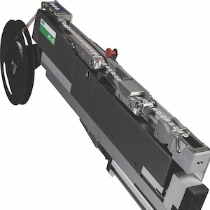
 Figure 3: Material deposition via inkjet.Multiple experiments were run on the inkjet tool to adjust parameters, such as DPI and layer count to print precise thicknesses of both clad and core layers. Table 1 shows the variation of the DPI settings versus bottom clad layer thickness from the Inkjet deposition tool. Thickness measurements using cross sectioning show very good control of the tool. This research was then used to determine the processing parameters to achieve the desired thickness.Based on Table 1, several experiments were done to target the desired thickness of the clad and core layers. Along with adjusting the mixture of the waveguide material, the temperature of the print head was also adjusted to produce the correct viscosity for material deposition.Figure 3 shows a substrate inside the inkjet tool at the beginning of the deposition process. Three subsequent deposition steps are done to deposit the bottom clad, core material and top clad material. To improve the adhesion of each layer to the previous layer, the panels are processed through a low power plasma process. Depending on the material used for the base substrate, this step may be needed prior to the first clad deposition step. Analysis of the surface energy showed that we were able to skip this plasma step for our RCC/Upilex substrates. EI experimented with various types of substrate preparation and found that the plasma process yields the best results and is the most manufacturable.
 Figure 4: A 62.5 micron waveguide cross-section.Waveguide Material Cure, Expose and DevelopOnce the waveguide material is deposited it needs to be both UV cured and thermally cured. For the clad layers, the UV cure is done with a blanket expose in the Tamarack expose tool. This energy is sufficient to expose the clad so it can then be thermally cured. The core layer is also exposed to define the waveguide pattern needed. This exposure is done using a specially designed optical mask. Great care is taken when designing these masks to give them the highest resolution possible and create structures with the lowest possible loss. To completely cure the layers of waveguide material, a cleanroom convection oven is used to heat the processed substrates for each layers. This oven is also used for pre-exposure bakes to make the waveguide material less tacky and therefore less susceptible to debris. Because optical waveguides are being manufactured, debris containment is very important and many steps were taken to limit contamination.During the formation of the waveguide channels, alignment holes are patterned in the core material on top of the copper pads. Since the alignment holes and the waveguide channels are created during the same lithographic step, the accuracy of the relative positions of these features is very good. To accomplish this alignment, the defined core material will act as an etch mask for the copper pad. For the core layer, once the desired pattern is exposed, the panel is processed through a develop process to define the waveguide pattern. EI built a custom develop tool for waveguide manufacturing. When the core layer is developed, the waveguides produced are fragile because they are not protected by the top clad layer. Because of these handling issues, EI decided to not use traditional spray tools for develop. The tool that was built instead uses submerged nozzles to create adequate solution movement without excessive impingement on the part. Developing is performed at room temperature for a length of time which produces square waveguides at the correct dimensions.Contamination ReductionAs with all optical waveguide manufacturing, the process development and technology transfer from IBM to EI has faced some issues regarding debris deposition onto clad and core layers. Any debris that lands onto the panels while the waveguide materials are in a tacky state will cause light scattering and high losses during final test. In order to eliminate this problem, EI has taken steps to limit contamination and prevent debris deposition onto optical surfaces. The first process implemented was to clean all of the substrates before the first layer of clad material is deposited. This is done by first wiping the substrates with a cleanroom cloth containing IPA and acetone and then chemically cleaning the surface by submersing the bare substrates into the develop solution. Careful consideration is also made to keep the substrates covered both when bare and once material is deposited. Special debris covers were made by EI to cover the parts anytime the waveguide material is in an uncured or semi-cured state. These covers are made from a filter material that was chosen for its ability to cover the parts and also let solvents escape during curing inside the oven. The filter material is also very thermal and chemical resistant. Other steps have been taken to eliminat contamination during curing. Teflon drawer inserts were added to the cleanroom oven in order to stem metal debris contamination experienced during curing steps. The bulk optical waveguide material is also well controlled and kept from gaining debris during material dilution steps. The cleanroom where the waveguides are produced is controlled and monitored for contaminant levels in the air. Proper gowning is also enforced inside the cleanroom to limit debris. Another step implemented to eliminate debris and improve yield is that the parts are now stored in a laminar flow hood between all of the process steps. This hood has a HEPA filter and constantly moves filtered air across the parts to remove debris that may fall onto the unfinished waveguides. A cross section photo of a finished waveguide bundle can be seen below in Figure 4. Post Waveguide Formation Process StepsTo attach the Optical waveguide assemblies to the PCB, EI developed a process using the core photomask and laser operations to define fiducials at the ends of the optical paths. These fiducials are defined after the waveguide formation process by using the core material as an etch mask. During the waveguide printing steps, the original copper markers defined during the substrate preparation are coated in core material and a hole is defined by the core photomask. After the waveguide production, this hole is defined in the copper markers by an etch process, using the core as a photomask. The final part of the waveguide flex build process is the laser profile and alignment hole definition process. Once the copper markers have been etched the substrates are put upside down into an ESI Flex 5330 Laser Drill/Profile tool at EI.
 Figure 5: Laser ablation of substrate beneath copper alignment holes.The laser is used to ablate slightly oversized holes in the Upilex substrate corresponding to the existing holes in the copper. Because the holes in the copper are the alignment fiducial, accurate centering of the Upilex holes on the copper holes is not necessary. Figure 5 shows the result of this process. These alignment holes provide accurate relative X and Y axes position of adjacent waveguide channels. Another use of these copper markers is to establish the Z axis reference plane for waveguide connectorization. Since the copper pads are laid on top of the RCC similar to the lower clad, once substrate materials are removed from the back side of these copper markers, the exposed copper surfaces of these markers are at the same height as the bottom of the lower clad. Therefore the holes in the copper marker will provide the X and Y location reference of the waveguide channels and the bottom of the copper marker pad provides the Z location of the waveguides. Thus accurate mechanical locating references for final assembly of the waveguides can be derived.
 Figure 6: Photos of framed part after laser profiling with tabs.Other uses of the holes defined in the copper markers are used as a reference to accurately position the laser-ablated turning mirrors and for laminating the flex waveguides onto a PCB. Precision pins placed through the holes in the copper markers are used to align the flex pieces during these operations.After the completion of the alignment holes in the copper markers, the waveguide singulation process follows. A laser ablation process is used to profile (i.e., cut) individual waveguides from the frame assembly. The waveguide profiling is conducted from the top (waveguide) side of the assembly. The profiling ablation pattern leaves small tabs between individual waveguides to prevent premature separation of the waveguides from the stainless steel frame. If these tabs are not used, some waveguides may detach from the frame assembly inside the laser tool causing damage to parts and processing problems. Figure 6 shows the results of the laser ablation process used to cut the waveguides from the frame assembly. Final removal of the waveguide assemblies from the substrate is done after removal from the laser cutting tool by cutting the tabs.Once the waveguide formation and singulation are finished, turning mirrors are laser cut into each waveguide. These mirrors are depicted in Figure 7 and are seen as the bright spots in the image, the waveguide was illuminated at the opposite end. Due to stresses built-up during the fabrication of these waveguides, a free standing waveguide will show significant curling. Clamping the flex around the edges did not provide the flatness that is required for accurate positioning of the mirrors. (The location of the turning mirrors does not maintain a straight line if the flex is not flat.) The practice, as developed by IBM, requires the lamination of a stainless steel stiffener to the bottom of each waveguide end. These stiffeners hold the waveguide ends flat and provide an adequately flat surface for cutting the turning mirrors. The stiffener plate is adhesively bonded to the bottom of the waveguide substrate using a Pyralux sheet adhesive. The Pyralux is laser cut to match the footprint of each stiffener; in volume production a steel rule die would be used. The use of a dry film adhesive provides for a cleaner process and provides for controlling the amount of adhesive between the stiffener and the substrate without the need to control for excess adhesive. The stiffener and the Pyralux preform contain holes that correspond to the hole in the copper marker. Just as for the hole that is formed in the Upilex substrate, the holes in the stiffener and Pyralux preform are slightly oversized to avoid the need for a precise mechanical alignment between them and the flex. Thus, the hole in the copper marker remains the fiducial for alignment between the flex and the FR4.
 Figure 7: Turning mirrors in WG.Once the turning mirrors are cut, a seal plate is placed on top of the mirrors to seal the entire area and prevent damage to the top clad surface in the area of the mirrors. A lens array is then attached to the top of the seal plate and aligned to the mirrors cut in the waveguide cores below. Both the seal plate and the lens assembly are bonded onto the top of the waveguide assembly with the use of a optically clear liquid adhesive that is UV-cured. An exploded view of the components in the waveguide end stack and a fully assembled waveguide end is shown in Figure 8. When the waveguides are complete and sent back to EI, the parts can then be processed through the optical loss measurement tools. This will be the final measurement to ensure that when combined with the Optocard and that the assembly will function. This measurement will be different from the previous optical loss measurements on waveguides without mirrors since we will be using the mirrors and lens as part of the optical pathway.Flex Waveguide to Optocard LaminationThe final step of the waveguide build process is attaching the flex waveguides to a PCB (Optocard). The stiffeners that were applied during the turning mirror process will remain in place when the waveguide assembly is attached to an Optocard. These stiffeners hold the waveguide ends flat and provide an adequate surface for lamination to the Optocard. A Pyralux preform is again used to bond the completed waveguide assembly to the Optocard. The alignment and bonding of the waveguide assembly to the Optocard is described in the following paragraph.
  Figure 8: Details of waveguide ends.The thickness of the stainless steel stiffener will raise the waveguide assembly too high to allow the subsequent attachment of the OE-MCM which contains the optical transceivers. To provide the necessary clearance, a pocket is milled out in the center of the BGA field where the waveguide ends are attached. With this pocket, adequate clearance is available between the lens array of the OE-MCM and the lens array on the WG assembly. The Optocard is locally milled out to a depth to accept the waveguide stiffener and Pyralux adhesive layer in a pattern only slightly larger than the stiffener.To position the flex assembly accurately on the Optocard, holes for standard MT ferrule pin diameters (0.7mm) are milled in the Optocard at positions that correspond to the holes in the copper markers on the waveguide assembly. These holes are placed with ~25um accuracy with an automated milling machine. The final positioning of the OEMCM (Optomodule) to the fully-assembled PCB will be based on a lens-to-lens alignment using a vision system. Since the BGA pads are 0.5 mm, the exact position of the alignment pins relative to the BGA pads is not very critical. The Pyralux preform is placed over the pins in the Optocard recess followed by the waveguide flex assembly. Clamping fixtures are then used to apply pressure to the waveguides ends where the Pyralux is placed. These fixtures apply pressure in a controlled way so that the waveguide seal plates and lens arrays are not damaged. The entire assembly is then baked under pressure to cure the Pyralux to complete the attachment. The fully assembled structure is shown in Figure 9.
 Figure 9: Waveguide flex attached to Optocard.The attachment process is repeated at the other end of the waveguide flex to complete the Optocard. A fully assembled Optocard is shown in Figure 10.
 Figure 10: Completed Optocard with flexible waveguide attached.Measurements of the completed waveguide assembly have shown the alignment of the integrated parts is within the allowable specification. These measurements are of where the turning mirrors are located with respect to the guide pins. The guide pins also bring the location back to the BGA pads on the Optocard. These measurements are within the allowable tolerances needed to locate the turning mirrors to the BGA pads. This is critical to creating a functional Optocard assembly.Loss Measurement SetupA measurement system, shown schematically in the following figure, is used for characterization of the waveguides fabricated at EI. We have achieved loss in the range of 0.05 dB/cm at 850 nm. A tunable 850 nm laser is used as the light source coupling into a single mode 850nm tap coupler. The coupler splits the incoming laser power into 10% and 90%.
 Figure 11: Schematic of loss measurement.Realtime laser power monitoring is accomplished by using the 10% tap together with a calibrated power meter. The 90% is used for loss measurement by launching the laser light into the waveguide with a cleaved SM 850nm optical fiber end butt coupled to the waveguide. The "raw" loss measurement is acquired directly from the exit end of the waveguide using a larger area photo detector. In order to isolate and quantify the actual loss of the waveguides, it is also necessary to obtain a set of similar loss measurements using a reference, a short waveguide of similar construction and geometry. This "reference measurement" is used to cancel out the coupling loss Lc inherent in this measurement technique by assuming the coupling loss Lc is consistent between waveguides with similar construction and geometry. Thus the resulting loss measurement delta can be attributed to the waveguide length difference in the two cases. Experimentation results thus far confirmed the validity of this assumption.Both sides of the waveguide facets have to be polished before the loss measurement process. An automated process is being developed to speed up the polishing steps. The polished waveguides are mounted in a fixture for loss measurements. The fixture is placed onto a positioner with two manual adjustable stages that offer rough adjustments in the vertical and the traverse axes. A 850nm SM bare fiber held in a precision three axes fiber positioner with submicron manual adjuster is used to launch laser light into the waveguide. Index matching oil is used at the butt coupling interface between the fiber and waveguide to assure coupling consistency.The work described in this paper is part of the Terabus program, while we are only partially through the program, the Endicott Interconnect/IBM team feel that the steps taken to date show that a viable low cost optical hybrid can be achieved. In performing the process development for this work, we realized that it will be feasible to build the Optical waveguides using standard PCB processing equipment. The remaining work will be to optimize the processes and further define the process windows for the critical process steps. This will provide a method of creating pre-tested optical waveguides externally attached to a PCB. The next step in the development will be to integrate the waveguide within a PCB.
 Table 1: Material deposition thickness versus DPI.
AcknowledgementsThe Endicott Interconnect team would like to acknowledge the following people at IBM: Jeff Kash, Russ Budd, Roger Dangel and Frank Libsch for their assistance in this work. References:1. B. Offrein, C. Berger, R. Beyeler, R. Dangel, L. Dellmann, F. Horst, T. Lamprecht, N. Meier, R. Budd, F. Libsch, and J. Kash, "Parallel optical interconnects in printed circuit boards," Proc. SPIE, vol. 5990, pp. 117- 125, 2005.2. T. Lamprecht, F. Horst, R. Dangel, R. Beyeler, N. Meier, L. Dellmann, M. Gmür, C. Berger, and B. Offrein, "Passive Alignment of Optical Elements in a Printed Circuit Board," presented at 56th Electronic Components and Technology Conference (ECTC 2006), San Diego, 2006.
Share on:


